Durable foundations rarely come from a single magic product or a clever trick on site. They come from interpreting drawings correctly, anticipating how the soil and climate will treat the concrete over decades, and aligning materials, sequencing, and site practices with what the structural engineer intended. The details on a foundation plan or section are more than lines. They are performance instructions. Reading them with the right eye saves concrete building foundations from early cracking, moisture infiltration, settlement, and costly callbacks.
I have walked more basements and crawlspaces than I can count, many of them built by conscientious concrete contractors and concrete companies that did most things well. When problems showed up, they usually traced back to a handful of misread or missed details. A vapor barrier tucked short of the footing-to-slab joint. A poorly cured edge where sunlight and wind pulled moisture from the surface. A dowel schedule read as “typical” when it was “at corners only.” The drawings told the story, but the crew on site needed a translator. This article is a translation guide: how to read and act on foundation details so concrete slabs and walls reach their full potential for concrete durability.
Reading the drawings with a durability lens
Structural drawings are designed to convey geometry, loads, and reinforcement. Durability lives between those lines. On a foundation plan, look for more than dimensions. Note where sections are cut and cross referenced. The section cuts are durability hotspots. They show slab-to-wall interfaces, vapor barrier laps, insulation layers, waterstops, keyways, and the grade relationship to exposed concrete.
On most sets, you will find general notes that address concrete best practices: minimum concrete strength, maximum water-cement ratio, air content if the concrete is exposed to freeze-thaw, and curing requirements. Those notes matter. A mix specified at 0.45 w/cm with 5 to 7 percent air is not a suggestion in cold climates. It is the difference between a tight, freeze-resistant surface and a checkerboard of scaling after two winters. When a note conflicts with the ready-mix plant’s standard mix or the schedule when temperatures are low, raise your hand. The earlier the discussion, the fewer compromises later.
The details also reference standards and tolerances. Flatness and levelness (FF/FL) for slabs, cover requirements for reinforcing, and spacing limits for crack control joints are not just about aesthetics. They tie directly to shrinkage performance, deflection control, and the ability of finishes to bond. When you interpret these details, focus on three risk zones: the top 25 millimeters of the concrete surface, the slab edges and corners, and the interfaces where concrete meets soil or another material. Most early-life durability failures begin in one of those three zones.
Footings, soil, and load paths
Before thinking about concrete, think about the soil it sits on. Foundation details often specify a bearing capacity or call out a geotechnical report. That report is not background reading. It defines the subgrade preparation, the need for over-excavation, and whether drains or under-slab vapor management are required. If the drawing shows a continuous footing at 600 millimeters wide on medium-dense sand with 150 kilopascals allowable bearing, the soil needs https://www.animenewsnetwork.com/bbs/phpBB2/profile.php?mode=viewprofile&u=1140920 to be in that condition after excavation and replacement. Pumping fines in wet weather, or leaving spoil smeared across the bearing surface, undermines the assumed capacity and increases settlement.
For strip footings and isolated pads, reinforcement placement is commonly shown near the bottom to resist tension from soil uplift and bending. The clear cover, usually 75 millimeters for cast-in-place concrete in contact with soil, protects against corrosion. I measure cover rather than eyeballing it. Chairs, dobies, or bar supports should be specified and actually used. When concrete contractors substitute rocks or broken block for support, bars end up too low, cover disappears, and the first aggressive groundwater event starts corrosion cells. That is not a theoretical risk. I have seen T12 bars rusting within five years where cover measured less than 20 millimeters.
Where the drawings show keyways between footing and stem wall, understand what they do and do not do. A keyway creates shear transfer and helps locate the wall, but it is not a waterproof feature. If hydrostatic pressure is a concern, the details should show a waterstop at cold joints, or a bentonite strip, or an integral crystalline treatment. If they do not, ask the engineer to clarify. Relying on a keyway alone to stop water is wishful thinking.
Stem walls, piers, and re-entrant corners
Concrete walls and grade beams crack where geometry concentrates stress. Re-entrant corners, doweled openings for services, and steps in grade all deserve careful interpretation. Look for additional bars around openings, diagonal bars at corners, and lap lengths that meet or exceed code. Drawings often hide these notes in a corner of the reinforcement plan or a detail bubble. When paired with a joint layout that lets the concrete move, these bars keep cracks tight and controlled.
Lap lengths are not negotiable suggestions. They are functions of bar size, concrete strength, and location (top cast versus bottom cast). If the detail says 600 millimeters splice for a T16 bar in a wall, do not tag on 300 because “it looks good.” Short splices are invisible until the wall takes a lateral load and a diagonal crack rakes through the splice line.
Anchorage between the wall and the slab, often shown with dowels or continuous bars, deserves similar attention. If the slab is structurally tied to the wall for lateral resistance, those dowels cannot be skipped just because forming them is slower. On the other hand, in slabs designed to float, tying into a wall can create restraint that drives random cracking. Read the design intent. Ask whether the slab is intended to be isolated with compressible filler at the perimeter and slip dowels at control joints, or fully connected. I have seen garages designed as isolated slabs that ended up doweled to frost walls, only to crack in long uncontrolled patterns because thermal and shrinkage movement had nowhere to go.
Slab-on-ground: from subbase to saw cut
A durable slab-on-ground begins long before the concrete truck backs up. The subbase needs uniformity more than strength. I prefer 100 to 150 millimeters of well-graded aggregate compacted to a firm, unyielding surface. Over-compact and you can lock in a corset that increases curling, especially under low humidity. Under-compact and you invite differential settlement that telegraphs into racking doors and cracked tiles.
Vapor control under slabs varies by occupancy and climate, but the detail should be specific. If the space is conditioned or receives moisture-sensitive flooring, a vapor retarder with a perm rating less than 0.01 should be placed directly under the slab or separated by a thin, dry-blotter layer only when expressly allowed. Lapping the barrier 150 to 300 millimeters and taping seams, then sealing around penetrations, seems fussy until you stand in a new building with a cupped hardwood floor and 85 percent relative humidity at the slab surface. That scene costs far more than an extra hour of poly and tape.
Reinforcement for slabs depends on whether the slab is unreinforced with saw-cut joints for crack control, lightly reinforced for crack width control, or post-tensioned. Each approach has trade-offs:
- Unreinforced, jointed slabs perform well for many light commercial and residential uses but depend heavily on timely, well-placed joints. Keep panels as close to square as the layout allows, and place joints over thickness changes, re-entrant corners, and utility trenches. Delay cutting beyond the first 4 to 12 hours, depending on mix and temperature, and you gamble. I have repaired too many early random cracks that traced to a morning delay when the crew got pulled to another task. Light reinforcement, such as a grid of T10 bars at 300 millimeters, does not stop cracks. It holds them tight. That allows slightly wider joint spacing, reduces curling at edges, and helps slabs perform under point loads. For forklift aisles or slab areas with racks, this is often worth the incremental cost. Post-tensioned slabs reduce cracks by placing the concrete in compression. They require disciplined stressing, proper tendon profiles, and attention to penetrations. When the detail shows additional top steel at openings or column blockouts, it is not decorative. Fit it.
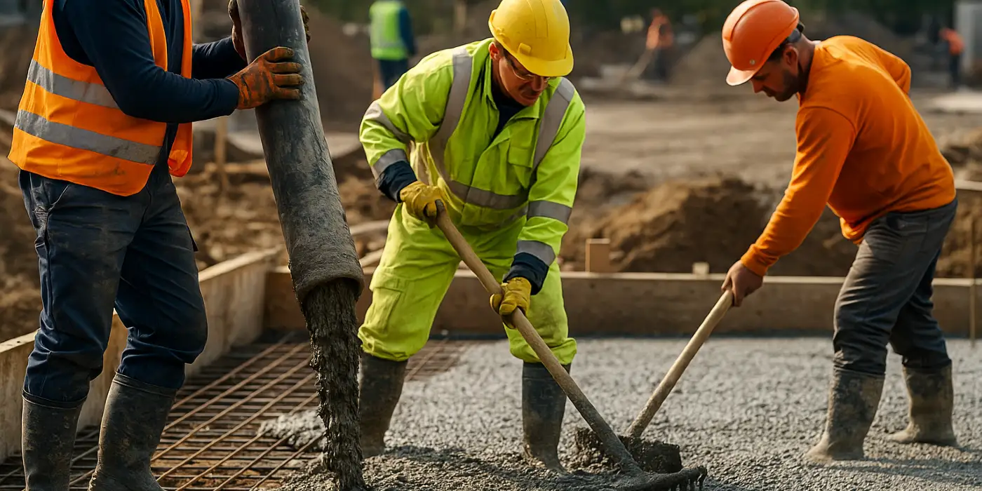
If the drawing calls for a specific flatness and levelness, align finishing methods with that goal. Screeds and laser screeds are modern concrete tools that help meet FF/FL targets, but only if the crew controls mix consistency, manages bleed water, and times finishing. Troweling a slab with bleed water on the surface traps moisture, weakens the paste at the wear layer, and invites dusting and surface map cracking. If the air temperature and wind are high, an evaporation retarder spray and windbreaks keep the surface workable without adding water.
Concrete mix: what the numbers mean for durability
Concrete companies offer standard mixes, but the drawings and specs adjust them for exposure. For slabs and walls that face deicing salts, an air-entrained mix is not optional. Target 5 to 7 percent air by volume for 19-millimeter aggregate and standard slump. Do not assume the air content at the plant is what you get at the chute. Retest onsite if the haul time is long or if water is added.
The water-cement ratio drives permeability and shrinkage. Ratios from 0.40 to 0.50 are common for durable exterior elements. When specs cap w/cm at 0.45, adding water on site to “loosen it up” sabotages the design. Better to use a mid-range water reducer to improve workability without changing the ratio. Supplementary cementitious materials, such as 20 to 30 percent fly ash or 35 to 50 percent slag cement, can improve sulfate resistance, reduce heat, and lower permeability. The trade-off can be slower strength gain, which means you should plan for later saw cuts or use early-entry saws to avoid uncontrolled cracking.
For hot weather, watch mix temperature and slump loss. For cold weather, ensure the concrete is delivered warm enough, and protect it from freezing until it reaches at least 3.5 to 7 MPa, depending on exposure. Most curing failures in cold snaps come from insufficient insulation or curing blankets pulled too soon at slab edges. Inspectors often check internal temperatures only in the middle of the placement, while edges radiate heat and drop below safe thresholds.
Joints, waterstops, and the art of where to let it move
Cracks happen when concrete wants to change volume and is restrained. Joints are the plan for where it happens. The drawings should show four kinds: construction, control, expansion, and isolation. The terms get misused on site, so line up definitions.
Control joints (saw cuts or tooled) create weakened planes to attract cracks. Cut them to a depth of one quarter to one third of slab thickness, as early as the mix and ambient conditions allow without raveling. In sloped slabs, use depth rather than minimum to ensure efficacy. If the slab varies from 100 to 150 millimeters, aim at 38 to 50 millimeters cut depth rather than a flat 25.
Construction joints occur between placements. Where traffic crosses them, details often show smooth dowels for load transfer. Dowels should be sized and spaced per the plan and aligned so they do not bind. I have seen misaligned dowels lock a joint and force cracks to jump diagonally into the slab panel. Drill a few pilot checks to verify alignment, and use basket assemblies if the crew is not experienced with dowel placement.
Expansion joints are gaps that accommodate thermal or moisture expansion, often at fixed elements like columns or abutting structures. Many slabs do not need true expansion joints, but when they do, compressible fillers and proper sealants keep debris out and allow movement. Isolation joints separate slabs from walls or footings. If the detail calls for 10 to 20 millimeters of compressible board at the perimeter, respect it. Tying a slab to a wall intended as an independent element creates restraint and tears finishes later.
For water-bearing elements or where hydrostatic pressure exists, waterstops at construction joints are not extras. PVC ribbed waterstops, stainless steel waterstops, or hydrophilic strips are shown in sections for specific reasons. I still encounter basement walls with cold joints at lift lines but no waterstops, relying on crystalline admixtures alone. Those admixtures can help, but they are not substitutes for physical barriers where water pressure is significant.
Curing: the cheapest durability insurance
Ask any old finisher about the best cure, and they will say water. Continuous wet curing for 7 days, or 70 percent of the design strength, produces denser, more durable surfaces. It is also hard to execute on busy sites. Curing compounds are acceptable substitutes in many applications, but you still need to prevent early moisture loss in the first day, especially at edges and around columns where heat sinks speed evaporation.
Plan curing like you plan formwork. If wind and sun are forecast, use evaporation reducers during finishing, apply curing compound at the earliest allowable time, and protect edges with blankets or damp burlap. Where flooring adhesives or coatings will be applied, confirm compatibility of the curing compound. I have seen owners grind off perfectly good curing membranes at great expense because the flooring manufacturer rejected them. When in doubt, wet cure or use a dissipating curing compound specified as compatible with the finish system.
Detailing for freeze-thaw, salts, and harsh exposures
Not all foundations see the same world. A garage slab in a cold region, a coastal footing near salt spray, and a basement wall against expansive clay each face distinct threats. Good interpretation adapts the details to those threats without wandering off spec.
In freeze-thaw regions with deicing salts, prioritize air-entrained concrete, edge insulation as specified, timely sealing after 28 days or when moisture content allows, and drainage that keeps meltwater from refreezing at the lip. Do not hard-trowel air-entrained slabs meant for salt exposure. A moderate finish leaves the entrained air intact at the surface, which is what resists scaling.
In sulfates or chloride-rich environments, look for concrete labeled as sulfate resistant or with low permeability. Increase cover to reinforcement and ensure joint sealants are chemical resistant. Where stainless dowels or epoxy-coated bars are shown, do not substitute plain steel because the budget is tight. Corrosion at joints is a common early failure point.
Against expansive soils, details often show deeper footings, void forms under grade beams, and free-draining backfill. The void forms create space for the soil to swell without lifting the concrete. They are not optional packaging to be left in the rain. Saturated void cartons lose capacity and collapse under the pour, which then bears directly on swelling clay. I have repaired heaved grade beams after a single wet spring because void form discipline broke down during a hurry-up pour.
Interfaces: insulation, waterproofing, and penetrations
The transition between concrete and everything else defines durability. Slab edges that poke out to form stoops, for instance, bridge interior heat to exterior cold. Where the details call for insulation at the slab edge, install it continuously, protect it from UV and pests, and coordinate with formwork so the insulation is not carved away to fit a screed or a curb machine. Lost edge insulation leads to condensation, cold floors, and freeze-thaw cycles right at the slab perimeter.
Waterproofing and dampproofing show up as hatches in sections. They are not interchangeable. Dampproofing slows vapor diffusion, while waterproofing resists liquid water under pressure. If the detail shows a fluid-applied membrane with a protection board and drain mat, build all three. Skip the drain mat, and hydrostatic pressure builds against the membrane. Backfill with angular aggregate and filter fabric, and ensure the footing drain is continuous to daylight or a sump with a working pump.
Penetrations for plumbing, electrical, and anchors should be sleeved and sealed per the detail, not chiseled in after the fact. Core drilling cracks propagate if reinforcement is cut. When penetrations must be added, scan and mark rebar, then provide repair details that restore cover and the barrier layers. On one project, a dozen post-installed anchors near a cold joint let water track along threads into a finished space. Injection and sealing cost ten times the labor saved by not using the original cast-in-place embeds.
Reinforcement placement: cover, spacing, and bar supports
Despite the advent of modern concrete tools, reinforcement placement remains a manual craft. Chairs spaced at 900 millimeters or less prevent sag in mats. Plastic-tipped chairs or composite supports avoid rust staining near surfaces. For walls, spacers keep bars off forms at the specified cover. A common error is to assume nominal form thickness equals cover, ignoring ties and tolerances. Measure. Use a cover gauge if you have one, especially at exposed surfaces.
Couplers and mechanical splices appear more often on congested foundations and retrofit work. When specified, confirm compatibility with the bar grade and diameter, and check installation torque or set screws per manufacturer instructions. In seismic zones, couplers may need to be Type 2 for full tension development. Swapping in a lower class coupler to save cost degrades ductility that the structural engineer counted on.
Testing, acceptance, and what to do when results wobble
Durability depends on both design and execution. Field testing provides feedback. Slump, temperature, air content, and cylinder breaks are the minimum. When breaks trend low, resist the reflex to panic or to accept poor strength as “good enough” without context. Check curing of cylinders, handling, and whether the mix design changed. Low breaks can come from cold, wet cylinders rather than weak concrete. If in-place strength is in doubt, maturity meters or pull-out tests provide direct answers without guessing. For vapor, calcium chloride or in-situ RH tests tell you when flooring can proceed. Respect these numbers, or live with bubbled coatings and finger-pointing.
When cracks appear, not all are equal. Map crack width, length, and pattern. Hairline shrinkage cracks under 0.3 millimeters may be cosmetic. Wider cracks that cross reinforcement or invite water can be injected or routed and sealed. The detail to watch is whether the cracks align with joint layout. If not, evaluate restraint points, slab thickness changes, and curing records. The best repairs start with understanding the root cause, then improving the next pour rather than patching in the blind.
Coordinating drawings, specs, and the people who build
A set of drawings is one voice. The project specifications are another, and sometimes they disagree. The concrete section of the specs might say 0.45 w/cm and air-entrained, while the civil drawings show non-air-entrained for exterior flatwork. Resolve conflicts before placing orders. A 15-minute pre-pour conference with the ready-mix supplier, foreman, and inspector is worth hours of rework. Lay out joint locations with paint where they must fall relative to columns and openings. Confirm curing methods, protection plans, and test procedures. Assign one person to watch the surface for evaporation and plastic shrinkage, not just to run the screed.
Coordination extends to sequencing. If underground utilities chase the foundation crew, trench patches under slabs become weak lines. The detail that calls for thicker concrete or extra reinforcement over trenches exists because backfill settles and compacts differently. Compact lifts in thin layers, proof-roll if allowed, and consider doweling across trench edges if traffic will be heavy.
Simple field habits that pay off
Durability is a series of small wins. The best concrete contractors build habits that stack those wins.
- Verify subgrade moisture and temperature in the morning, then adjust curing tactics and saw-cut timing rather than working the same playbook every day. Photograph reinforcement and embeds with a tape measure in frame, so you can defend cover and placement later and avoid guesswork if repairs are needed. Protect fresh slab edges from sun and wind with temporary curtains or even parked trucks placed as windbreaks when nothing else is available. Keep finishing tools clean and reject any bucket of water that becomes a temptation to splash onto the surface. Walk the slab with the joint plan in hand and mark saw-cut routes before the saw arrives, so the operator does not improvise around obstacles.
None of these habits are heroic. All of them protect the top few millimeters of concrete and the interfaces where failure starts.
Where modern tools help, and where judgment still rules
Modern concrete tools have improved consistency. Laser screeds hit FF/FL numbers routinely. Rebar scanners reduce accidental cutting. Early-entry saws let you get ahead of shrinkage. Moisture meters and maturity sensors make decisions less subjective. These are all useful. They do not replace the need to read details and understand intent.
A laser screed can deliver a flat surface to the wrong elevation if the control points are off. A moisture meter is only as good as its calibration and the operator’s understanding of what “dry enough” means for a urethane adhesive. Early-entry saws still need appropriate depth and timing. New technology saves labor and increases quality when paired with the basics: good subbase, appropriate mix, honest curing, and clear communication.
A brief case study: the slab that wanted to crack
On a distribution center, 150-millimeter slabs over 150 millimeters of crushed aggregate were designed with light reinforcement and saw-cut joints at 4.5 meters. The drawings called for vapor retarder directly under the slab only in office areas. The contractor used a retarder across the whole footprint to simplify procurement, then placed the slab during a windy week. Saw cuts were planned for the morning after each pour.
By dawn, random cracks had appeared, mostly near the perimeter and around column blockouts. The crew had to route and seal dozens of cracks and re-cut joints to chase them. After a tense meeting, we changed three things. We switched to an evaporation reducer and windbreaks, increased early-entry saw use to the same evening, and backed down the finishing aggressiveness to avoid trapping bleed water. Cracking nearly vanished on the next placements. The drawings did not change. Our interpretation and execution did.
The lesson: details give direction, but weather and logistics push back. Adjusting the means to honor the intent, rather than forcing a standard routine, is what delivers durable outcomes.
Closing guidance for lasting concrete durability
A durable concrete building foundation is not a mystery. It is the sum of well-chosen details, faithfully executed. Read section cuts for interfaces and water paths. Respect cover and lap lengths. Choose mixes aligned with exposure and control water on site. Place joints where the slab wants to move, and cut them on time. Cure like it matters, because it does. Use modern tools to support the basics, not replace them. And when something looks off on the drawing or in the field, ask. The best concrete companies keep that dialogue open, because they know the cheapest fix is the one you make before the concrete leaves the chute.
Done right, concrete slabs and walls become quiet parts of a building. They carry loads, block moisture, and vanish into the background for decades. That is the goal. Structural clarity, applied with craft, gets you there.
Name: San Antonio Concrete Contractor
Address: 4814 West Ave, San Antonio, TX 78213
Phone: (210) 405-7125
This is the logo of San Antonio Concrete Contractor https://sanantonioconcretecontractor.net/assets/san-antonio-concrete-contractor-san-antonio-tx-logo.png
San Antonio Concrete Contractor is a local business located at 4814 West Ave, San Antonio, TX 78213
San Antonio Concrete Contractor serves consumers with residential and commercial concrete projects
San Antonio Concrete Contractor offers free quotes and assessment
San Antonio Concrete Contractor phone number is (210) 405-7125
San Antonio Concrete Contractor has the following website https://sanantonioconcretecontractor.net/
San Antonio Concrete Contractor has the following google map listing https://share.google/d8wsdJhNohh11Oyi5
San Antonio Concrete Contractor has this Facebook page https://www.facebook.com/profile.php?id=61581404267593
San Antonio Concrete Contractor has this twitter profile https://x.com/SanAntConcContr
San Antonio Concrete Contractor has this Pinterest profile https://www.pinterest.com/SanAntonioConcreteContractor/
San Antonio Concrete Contractor has the following Linkedin page https://www.linkedin.com/in/san-antonio-concrete-contractor-846606388/
San Antonio Concrete Contractor has this Youtube channel https://www.youtube.com/@SanAntonioConcreteContractor
San Antonio Concrete Contractor serves residents near Thomas Jefferson High School
San Antonio Concrete Contractor provides services near The Alamo.
San Antonio Concrete Contractor helps residents close to San Antonio Police Department at 3635 E Houston St, San Antonio, TX 78219